Wednesday, September 20, 2017

BSide ADM04 Mini Multimeter Review & Teardown

The BSide ADM04 mini multimeter is a 3 1/2 digit small and inexpensive portable digital multimeter with some special features. One of the features is the non-contact voltage detection (NCV) function. This enables you to locate hidden live mains wires behind a wall. The ADM04 mini also has a Hold function and LCD backlite, something that even some more expensive multimeters don't have. But that's not all, it also has a spotlight! Yes, press a button and you can turn your multimeter into a flashlight. So, this is clearly a multimeter ideally suited to be carried around. Lets take a closer lock at the BSide ADM04 mini multimeter.

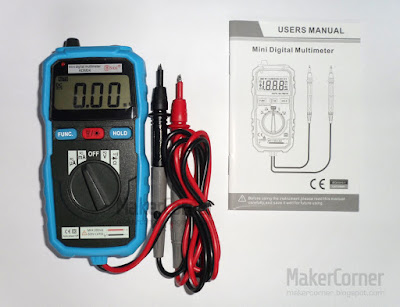
BSide ADM04 mini multimeter

Features:
3 1/2 digital LCD display.
Mini pocket Auto range digital multimeter.
Measure DC/AC voltage, DC/AC current, resistance, and diode & continuity check.
Data Hold function.
With NCV (Non-contact AC voltage detector) function.
With backlight and work light.
With protection case.
Low battery indication.
Auto power off.
Safety rating: CE CATIII 600V.

Specifications:
DCV: 200mV/2V/20V/200V+-(0.5%+3), 600V+-(0.8%+5)
ACV: 2V/20V/200V+-(0.8%+3), 600V+-(1.0%+5)
DCA: 200µA/2000µA/20mA/200mA+-(1.8%+5)
ACA: 200µA/2000µA/20mA/200mA+-(2.0%+5)
Resistance: 200Ω/2kΩ/20kΩ/200kΩ/2MΩ+-(1%+3), 20MΩ+-(1.2%+15)

General characteristics:
Operating Temperature & Humidity: 0~40°C(32~104 °F), <80% RH
Storage Temperature & Humidity: -10~60°C(14~140 °F), <70% RH
Product Size: 130x62x27mm(5.4"x2.5"x1.10")
Product net weight: 150g/0.34lb
Colour: Black + Blue
Power Supply: 2 x 1.5V AAA Batteries (NOT included)

Appearance
The first thing that catches your attention is the small size of the BSide ADM04 multimeter. Although not the World's smallest multimeter, it will fit a large pocket. The multimeter case is protected by a silicone sleeve. The silicone sleeve protects the multimeter from falls and prevents the multimeter from skidding on the work bench. You will also notice that the test leads are not the usual detachable banana type cables, but are instead attached permanently to the multimeter. Since the ADM04 does not have some functions that would require the use of more than two multimeter inputs, for example high currents measuring, there is no need for detachable multimeter test leads. The test leads appear to be of good quality. The probes have detachable sleeves.

BSide ADM04 mini multimeter backlight

Non-contact voltage detection function
To use the non-contact voltage detection feature put the multimeter rotary switch in any position other than Off and point the bumpy part of the top of the multimeter to where the wires would be. If live AC wires are detected an LED near the top of the LCD will turn red. My tests show that the multimeter can detect live AC mains wires behind walls as long the wires are not to far away or the wall is not made of cement. Mains wires should be easily detected in plaster walls. Detection distance will vary, but it should work at a distance of up to about 10cm.

Voltage test
Both DC and AC measurements where within the accuracy specifications.

Current test
Current tests where within the accuracy specifications. Note that the ADM04 multimeter is capable of measuring only up to 200mA maximum current.

Diode test
Diode test range is 1V with 0.001V resolution and about 1mA test current. The display shows the approximate value of diode forward voltage drop. Open circuit voltage is about 1.6V which will be a problem when testing some LED's.

Continuity test
The built-in buzzer sounds when the measured resistance is less than about 50Ω. Response time is not fast, but it's OK.

Hold function
Reading values can be frozen on the LCD by pressing the hold button. The multimeter does not have auto-hold function.

Backlight and flashlight
LCD backlight is turned On by pressing the backlight button for 2 seconds. Backlight turns Off automatically after 15 seconds. The flashlight consists in a white LED with a lens and is activated simultaneously with the LCD backlight.

Test leads
The test leads are rated 600V CATIII/1KV CATII. They appear to be of reasonably good quality and made from silicone wire. The probes have detachable sleeves.

Battery replacement
The BSide ADM04 mini multimeter is powered by 2x AAA batteries. The battery compartment can be opened by removing a screw on the back.

Fuse replacement
The multimeter uses a single 250V 250mA ceramic fuse. To replace the fuse it is necessary to open the multimeter case.


Tear-down
The multimeter can be opened by removing the protective rubber case and unscrewing four screws. The battery compartment connects to the main board by two springs.

BSide ADM04 mini multimeter battery replacement

The multimeter uses a single board design. Component layout is good without any bodge wires in sight. Soldering is also good.

BSide ADM04 mini multimeter main board pcb teardown

Input protection is accomplished by a single 250V 250mA ceramic fuse, two PTC's, diodes and resistors. Since this multimeter does not have a high current input, the usual wire current shunt and high current fuse are not present.


Verdict
The BSide ADM04 mini multimeter is a 3 1/2 digit portable digital multimeter with some welcomed added features and good build quality. The multimeter comes with a user manual in good English, something that more often than not is not the case. If you don't need to measure currents higher than 200mA, this is a good little multimeter to carry around. It is adequate for low voltage, low current circuits.


Need a better multimeter? Then take a look at my Uni-T UT61E multimeter review.
New to multimeters? Read my Multimeter buying guide.

Tuesday, August 29, 2017

BENJIE S5 / AGPTEK M20 Music Player Review & Teardown

This is a full review and tear-down of the Benjie S5 / AGPTEK M20 Hi-Fi music player. The Benjie S5 is a portable music player that has gained recognition from users for its sound quality and small price. The small player supports the most popular compressed and uncompressed audio formats: APE, FLAC, OGG, MP3, WMA, AAC-LC, WAV and ACELP. That means you can probably play all your music library without the need to convert any music files. The player has 8GB of internal memory and supports up to 64GB microSD cards. Playing time is 14 hours. The Benjie S5/AGPTEK M20 is also an FM stereo receiver and voice recorder.

If you play music on your cellphone, you probably can notice some interference noises. It's very difficult to suppress those unwanted noises on a cellphone. If you want better audio quality, a dedicated music player (like the Benjie S5/AGPTEK M20) is the way to go! 

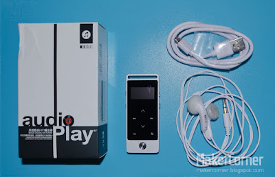
Benjie S5 Music Player, box, earphones & USB cable.

The heart of the Benjie S5/AGPTEK M20 player is the Actions Semiconductor ATJ2127 single-chip highly-integrated digital multimedia solution. The ATJ2127 includes an audio decoder, record capabilities and USB interface. It has a built-in Sigma-Delta D/A converter and includes a headphone driver to directly drive low impedance headphones. 

Specs
Supported music formats: APE, FLAC, OGG, MP3, WMA, AAC-LC, WAV and ACELP
Memory capacity: 8 GB (internal)
External memory: supports up to 64GB microSD cards
Playing time: 14 hours (by earphone)
Charging time: 2 hours
Battery capacity: 3.7V/280 mAh
Charging method: micro USB
Screen: OLED 1"
Firmware upgradable?: Yes
FM radio?: Yes

The player is sold under different brand names as Benjie S5, Benjie M20, AGPTEK M20 and probably others. Hardware and functionality is the same, however AGPTEK does provide firmware updates from their site while (at time of writing) Benjie does not provide firmware updates. It appears however that you can update your Benjie S5 branded player with the AGPTEK M20 firmware without issues. I have done the update without issues and it does provide some (minor) improvements. But, since no significant improvement has been made, I wouldn't bother updating at the moment.

The case is made from Zinc alloy with an aluminium back. There are no screws is sight, the back plate is held in place with double sided tape. I like the design, but I find the case edges a bit too sharp.


Benjie S5 Music Player back.

Interface 
The player fits the palm off your hands nicely and has nice (but not perfect) control interface. The front face has a small OLED screen, touch control interface and one physical play/pause/select button. Volume control has two dedicated buttons on the left side and the right side has an on/off button and a lock button. The touch control area has no backlight, which means you can't reliably access some functions in the dark. Fortunately, the skip and back functions are available through the Vol Up and Vol Down buttons when the screen is turned off. 

The user interface can be a bit confusing. There is some inconsistency in the use of the Up, Down, Previous, Next buttons when using the settings menu and the FM radio. Sometimes you expect to use the next/previous control, but the interface assigned the function to the up/down control intead. Overall however, the interface works reasonably well.
 
If, like me, you have not properly tagged all your music, you may like to know that the player has the Folder view option, where you just select the folder where the album you want to play is located and it will play all tracks in that folder.
 
The player uses its USB connection for charging and file transfer. File transfer is fast.

Audio quality 
What surprises me most about the Benjie S5 is the audio quality. Despite being a low cost entry level Hi-Fi player with a lowish D/A+PA SNR of only >91dB and a 16-bit Sigma-Delta D/A, listening to a wide range of music revealed that the Benjie S5 has very good sound quality. For even better sound quality you would need to pay more than double the price of the Benjie S5 or AGPTEK M20!

Frequency response seems flat, which is good. Using a good set of earphones or headphones the player has plenty of bass and highs even with the equalizer turned off. The Benjie S5/AGPTEK M20 can drive 16 Ohm, 32 Ohm or 64 Ohm headphones easily. It can also drive high sensitivity 100 Ohm headphones, but at a lower maximum sound level. If you want or need, you have 6 equalizer settings to choose from, but unfortunately no custom setting. 

The earphones included with my player deliver good but not great sound. These are all white and with a different cable than other earphones delivered with the Benjie S5. I suggest you get a better pair of earphones or headphones.

The sound on the Benjie S5/AGPTEK M20 is "clean", with no discernible noises. 

Gap-less playback 
Gap-less playback means a music player can play audio tracks without any silence (gap) between them. This means that you can listen to several consecutive tracks as it was one continuous single track. This is desirable because some albums have tracks that are meant to follow the previous track immediately, without the usual silence gap. Unfortunately the player is not capable of gap-less playback. The sound gap is very short, but it is noticeable. This is apparent, for example, on Steve Vai's Sound Theories Vol I & II. Not a deal-breaker though.

Screen 
The Benjie S5/AGPTEK M20 uses a small 1" OLED display. Despite the small size, the display is quite readable if your eyesight is good, but only indoors or in the shade. Like with so many other players, it's very hard to see the display outdoors on a sunny day. Besides battery level and play mode, the player displays track number, track name, album name, track duration and playback position, but it does not display file bit-rate or type. Only by file name you can know what type of file you are playing. 

Benjie S5 Music Player.

FM radio 
The Benjie S5, AGPTEK M20 has an FM Stereo receiver with 30 pre-sets. Reception with a strong enough signal is good, but weak stations may be hard to receive. FM radio function is performed by the RDA5807M IC. Although the RDA5807M is RDS capable, unfortunately the capability is not implemented by the current firmware. This means no RDS information is displayed and stations are named and memorized with their frequency value and not their name. Recording FM radio is also not possible. 

Benjie S5 FM radio.

Battery
The player uses its USB connection for charging the 3.7V 280 mAh Li-on battery using the provided micro USB to standard USB male cable. Charging time is 2 hours. I have not measured exact battery duration, but the claimed 14 hours seem reasonably accurate. Stand-by time is claimed to be 560 days.


Tear-down: 
Opening the player is not easy, the back is held with double sided tape.

Benjie S5 / AGPTEK M20 teardown.

With the back removed you have access to the Li-on battery.

Benjie S5 / AGPTEK M20 teardown.
 
The main board. Simple and tidy!
 
Benjie S5 / AGPTEK M20 teardown.

Removing the main board exposes the touch controller board, the OLED screen, internal memory, headphone connector and play/pause/select button.

Manufacturer product information 
Benjie S5, M20 product page
AGPTEK M20 product page
Action Semiconductor ATJ212X specs 

BUY THE BENJIE S5 FROM BANGGOOD

Note: I may get a small fee (at no extra cost to you) if you use the link to buy the player. Thank you for your support!

Saturday, June 10, 2017

DIY refrigerator door alarm

Today I will teach you how to make an excellent energy saving refrigerator door alarm for less than 2 USD.

It happens to everyone in every home around the World. You are about to open the fridge door and you notice that it was left open, often overnight!

When the fridge door is not shut tight the cold escapes and your fridge thermostat will make the motor (actually it's a compressor) run non-stop to try to maintain the cold temperature. Refrigerators are power hungry appliances and any unnecessary energy consumption is a waste that adds to your electrical bill and harms the planet!

Remember that about 2/3’s of all electrical energy is generated by heavily polluting sources like coal, gas and oil. So, any waste should be avoided to help preserve our planet!

This problem affected our home, so I looked for a solution. I searched for refrigerator or fridge alarms but, surprisingly I could not find an effective refrigerator alarm. I did found an alarm that replaces the fridge light bulb, but there are two potential problems with this solution. Since the light bulb replacement alarm is placed inside the fridge it may not be always be heard and (equally bad) the alarm may not be activated if the door is only partially opened, which is what usually happens. This lead me to consider developing a fridge door alarm that would be reliable, easy to build and cheap. But then I remembered I had some cheap window/door alarms in my “Made in China” gadget bin. Why reinvent the wheel when a solution is already available? Surely they could be hacked to work as a refrigerator alarm, right? Well, as a matter of fact they can!

A DIY REFRIGERATOR ALARM FOR UNDER 2 USD

After some experimentation I found that “standard” window/door alarms could be used as refrigerator door alarms with a simple “mod” or “hack”. These alarms are very small and come with double sided tape for easy attachment. They are loud and durable. I have made this hack a few years ago and it still works reliably. With the suggested hack the batteries (3x AG13) can last for years without needing replacement.

Window and Door Alarm
Generic Window/Door Alarm

HOW IT WORKS

These alarms use a magnet to switch the alarm on or off. Inside the alarm there is a reed switch which consists of two flexing metal contacts inside a small glass container. If the magnet is near enough the alarm, the reed switch contacts touch each other and the alarm will not be triggered. As soon the magnet is removed, the reed switch contacts open, the alarm is triggered and a loud chirp will sound immediately.

Window/door alarm components
1. Inside a window/door alarm.

THE WINDOW/DOOR ALARM HACK

My hack consists in introducing a delay in the alarm triggering circuit, so that the alarm will not be triggered immediately, but only after a certain amount of time. 

Alarm delay circuit
2. Alarm trigger delay circuit.

This delay is determined by the values of capacitor C1 and resistor R1. Point P1 is at low logic level (ground). When the magnet is near the reed switch, the contacts are closed and point P2 is also placed at a low logic level state. When the magnet is distanced from the reed switch, the reed switch contacts open, point P2 is no longer grounded and C1 begins to charge. When C1 reaches a certain minimum charge level, P2 goes into high logic level state and the alarm is triggered. I determined that about 1 minute was the ideal alarm delay time, but you can make the alarm sound earlier or later than 1 minute by using a capacitor with a different value. A bigger capacitance value will increase the alarm delay time. A smaller capacitance value will decrease the delay time.

Parts:
Windows/Door entry alarm (< 2 USD)
C1 22µF 10V electrolytic capacitor (for 60s delay)
R1 2.2K 1/4 W resistor
R2 100K 1/4 W resistor

To make this “mod” or “hack” you will need a low power soldering iron. A multimeter or voltmeter is recommended but not essential.

Notes:
  • The capacitor can have any voltage rating above 6V, but above 25V it may not fit inside the alarm plastic enclosure.
  • The resistor values are not critical, you may use approximate values.
  • You can use salvaged resistors and capacitors from old or faulty electronic devices (radios, computer peripherals, etc).

Step 1 – Buy a window/door alarm

These small alarms are very cheap and can be found on many places. On the Internet you can buy them on eBay, Banggood, Dealextreme, and many other sites and with free shipping. Locally you can try Pound shops (in the UK), 99 cents stores (US) and many other stores that sell cheap Chinese electrical and electronic items. You may support this blog by buying from DX or Banggood. Your support is appreciated.

Step 2 – Test the alarm

Place the magnet next to the alarm and align the by the markings on the alarm and the magnet. Turn the small on/off switch to the on position. The alarm should remain silent. Now move the magnet away from the alarm. The alarm should be triggered and sound very loud. Turn the alarm off.

Step 3 – Open the alarm enclosure

Open the battery compartment and unscrew the small screw located bellow the battery compartment.

Step 4 – Make the following modifications to the alarm circuit


Window/Door Alarm Hack
3. Hacked window/door alarm solder points.

1 - Perform a continuity test (with a multimeter) between the battery compartment negative contact (blue wire) and points 1 and 2. One of these points should show a short to the battery negative contact. Take note of which point (P1 or P2) is connected to the battery negative contact.  

2 - Solder one lead wire of a 22 µF electrolytic capacitor to one of the points (1 or 2), making sure to respect capacitor polarity. For example: if point 1 is connected to battery negative, then solder the capacitor negative lead wire to point 1 or the capacitor positive lead wire to point 2. The polarity of electrolytic capacitors is marked with a stripe or a ( - sign) along the negative lead.

3 - Solder one lead wire of a 2.2K Ohm resistor to the other point. Trim excess lead wires and solder the resistor to the other capacitor lead wire. When soldering is finished it should look like image 4.

As it is the alarm should now work with a delay of about 1 minute. Test it.

The alarm is now ready to be installed on your fridge. But, if you find the alarm too load you can add a resistor (R2) between the speaker (piezo buzzer) and the circuit board.

Window/Door Alarm Hack
4. Hacked window/door alarm for refrigerator door.

To reduce the loudness of the alarm:


Take note where the two buzzer wires are soldered on the circuit board.
De-solder one of the wires from the circuit board.
Solder a resistor (R2) to the point on the board where the speaker wire was connected before.
Solder the other lead of R2 to the disconnected speaker wire (point 5).

The suggested resistance value for R2 should lower the alarm sound volume considerably, but still make it clearly heard. However, you can try different values until you get the volume you want.

FRIDGE DOOR ALARM INSTALLATION

You can place the alarm anywhere alongside the refrigerator door. However, it is best to place it high on the door. This way you can easily reach the manual switch to switch the alarm off, in case you need to clean your fridge.
 
These alarms come with double sided tape attached. Remove the protective paper from the tape and press the alarm aligned with the edge of the fridge cabinet.

Now you need to attach the magnet to the fridge door. Here we must be creative, since the distance from the fridge door to the fridge (and the alarm) is too big. You can use a piece of clear acetate film and attach the magnet to one side and attach the opposite side to the fridge door. You can hold the acetate film in place by putting it between the door handle and the door or using double sided tape. Before attaching to the fridge door, test the correct distance for alarm activation and de-activation. The switch can be heard clicking as you approach and distance the magnet from the alarm. The alarm should be triggered with the door barely open. Since the magnet is not going to be screwed you can cut both ends of its plastic housing. I did not bother since it is out of sight.

Window/Door Alarm Refrigerator
Hacked window/door alarm on refrigerator door.
Tips:
  • If your refrigerator as two doors you can use two alarms or attach the alarm to one door and the magnet to the other. If either of the refrigerator doors is opened, the alarm will be triggered.
  • If your refrigerator is not white but silver, just spray paint it with silver colour paint.
That's it. Your refrigerator is now protected against accidental door openings, saving you money on your electrical bill and at the same time helping to save the planet!
If you find this post / hack / tutorial helpful please use the post share buttons or leave a comment below.

Buy the parts
Buy the Window and Door alarm from Banggood
Buy the Window and Door alarm from Dealextreme
Buy 12 Values 120pcs Electrolytic Capacitor Pack from Banggood
Buy 12 Values 120pcs Electrolytic Capacitor Pack from Dealextreme
Buy 30 values resistor kit from Banggood
Buy 40 values resistor kit from Dealextreme

Friday, May 26, 2017

HC-05 Bluetooth module AT commands tutorial

Today we are going to learn how to read and change the programmed settings and information stored on the popular HC-05 Bluetooth module. In this tutorial we will learn how to check what firmware version is installed, change the device name, baud rate, etc. 

In part one we learned how to add two-way Bluetooth communication to the Arduino. If you missed it, please check it out here

Like similar devices, the HC-05 modules physically interface with other devices using a serial interface and AT commands. In fact, reading or changing the HC-05’s settings is very similar to reading and changing the settings of the ESP8266 Wi-Fi module, which I demonstrated on a previous post.


To access the HC-05 serial interface we use a USB to serial adapter. The connection is very simple, the transmit pin of the HC-05 connects to the receive pin of the USB to serial adapter and vice-versa and the GND (ground) and VCC pins connect to its counterparts. However we must be careful and use the same logic level used by the HC-05 module. Bare HC-05 modules (without breakout board) accept only 1.8 to 3.3V levels. Most (if not all) HC-05 modules with breakout boards also use 3.3V logic level, so a level adapter may be needed between the USB to Serial adapter TX pin and the HC-05 RXD pin if your USB to Serial adapter is only capable of using 5V logic levels. 
5V 3V Logic level adapter
If you don’t have a logic level adapter you can use a simple two resistor voltage divider, like we did in part 1 of the HC-05 tutorial. The HC-05 power supply voltage (VCC) must also be respected. If you use the wrong voltage, operation can be unreliable or the module destroyed!  


Step 1 - Connections
USB To Serial Adapter    HC-05 module
VCC ---------------------------> VCC
TX -----------------------------> RXD *
RX -----------------------------> TXD
GND ---------------------------> GND

* Voltage level must match! Use level converter or voltage divider.

Once the HC-05 is wired to the USB to Serial adapter, plug it in your computer.

Step 2 – Enter HC-05 command state
HC-05 Bluetooth modules can work in (normal) data state or in command state. Once powered, the HC-05 module led should start blinking. If the led blinks approximately every two seconds, it means the HC-05 module is in command state, ready to accept AT commands, which is what we want. If the led blinks very fast it means the HC-05 module is in data state, which we don’t want. 

HC-05 modules with a button seem to default to data state when powered, while modules without a button are wired to enter into command state when powered. Behaviour is not the same for all HC-05 modules!

Entering command state:
Disconnect VCC from the HC-05 module. Press the small button and, while pressing the button, reconnect VCC to the HC-05. After a few moments the led will start to blink at a slow rate. Stop pressing the button. The module is now in command state. If your HC-05 Bluetooth module doesn’t have a button you can enable command mode by applying 3.3V to the HC-05 KEY pin.

To communicate with the HC-05 module via the serial interface we use a serial communications (terminal) program. I will demonstrate using RealTerm. You can download RealTerm here.

Before we can start typing commands we must configure the port and baud rate in RealTerm.You can see what port is being used by your USB to Serial adapter in Windows Device Manager. Select the correct port. Most HC-05 modules appear to use a default baud rate of 38400. Select 38400. Then press the Change button.

The HC-05 serial interface requires a CR (carriage return) and a LF (line feed) at the end of every command. Set your serial terminal program to automatically send a CR+LF.

AT commands
Please note that HC-05 Bluetooth modules come with different firmware versions installed. This means that your module may use a slightly different syntax for some AT commands or it may have fewer or more AT commands than other modules. At the end of this tutorial I give some advice on how to get the AT commands list for your HC-05 Bluetooth module. 

HC-05 Bluetooth AT commands testing

Test the serial interface
Type “AT” and press Send. The HC-05 should respond with OK if the command is accepted. If garbled text is displayed, this means the baud rate setting in RealTerm is wrong. Change the baud rate and try again until OK is displayed.

Check firmware version
To know what firmware is installed on the device, type “AT+VERSION?”

Check serial parameters (baud rate)
To know what baud rate is being used by your HC-05 module, type “AT+UART?”. The module will return three parameters (Baud rate, Stop bit, Parity).

Set serial parameters (baud rate)
To change the baud rate, type “AT+UART=<param1>, <param2>,<param3>”. Params are Baud rate, stop bit and parity.

Restore default parameters
To restore the HC-05 to factory default settings type “AT+ORGL”.

Bluetooth Masters and Slaves
Connected Bluetooth devices form networks that are commonly referred to as piconets. And Bluetooth uses a master/slave model to control when and where devices can send data. A single master device can be connected to up to seven slave devices, but a slave device (in the same piconet) can only be connected to a single master. 

The master device coordinates the communication throughout the piconet. It can send data to its slaves and request data from them. Slave devices are only allowed to transmit to and receive from their master. They can’t “talk” to other slaves in the piconet.

Master or Slave?
To know if the module is set as “Master” or “Slave”, type AT+ROLE?
The HC-05 will return 1 for Master or 0 for Slave.

Set HC-05 as “Master”
To set the HC-05 as “Master”, type “AT+ROLE=1”.

Set HC-05 as “Slave”
To set the HC-05 as “Slave”, type “AT+ROLE=0”.

Check connect mode
To check what connect mode is enabled type “AT+CMODE?”
The HC-05 will return: 0 (predefined address), 1 (any address) or 2 (slave loop).

Set connect mode
To set connect mode, type “AT+CMODE=<param>”. Where “<param>” can be 0 (fixed address), 1 (any address in range) or 2 (slave-loop).

Get working sate
To get the working state, for example, to know if the Bluetooth module is paired or not, type “AT+STATE?”. The HC-05 will return: “INITIALIZED”, “READY”, “PAIRABLE”, “PAIRED”, “INQUIRING”, “CONNECTING”, ”CONNECTED”, “DISCONNECTED” or “NUKNOW”. 

Get pin code
To pair Bluetooth devices a pin code is requested for the authentication process. All HC-05 modules seem to come with a “1234” default pin code. But, if the default code was altered it can be read by typing “AT+PSWD?”.

Set pin code
To change the pin code type “AT+PSWD=<newpincode>”, where “<newpincode>” is the pin code to be set.

Check HC-05 module name
To know what name the module is using, type “AT+NAME?” while the module button is pressed.

Set the HC-05 module name
To set the module name type “AT+NAME=<newname>”, where “<newname>” is the new name to be used by the HC-05.

To get your module’s complete list of HC-05 AT commands and specs, go to the manufacturer website. If you don’t know the manufacturers name try searching by the string returned by the “AT+VERSION?” command. The module used in this tutorial returned “H-C-2010-06-01” which pointed to ITeadStudio.com where I got the HC-05 AT commands list.

Buy the parts
Buy the HC-05 Bluetooth module from Banggood
Buy the USB to Serial Adapter from Banggood
Buy the HC-05 Bluetooth module from Dealextreme
Buy the USB to Serial Adapter from Dealextreme
Buy the Logic Level Converter from Banggood
Buy the Logic Level Converter from Dealextreme

I may get a small fee if you use the links to buy the parts. Thank you for your support!
 
Documentation
HC-05 Bluetooth Specs and AT commands list

PART 1: Arduino Two-Way Bluetooth with HC-05 module

Friday, May 12, 2017

Arduino Two-Way Bluetooth with HC-05 module

Today we are going to learn how to establish two-way Bluetooth communications between an Arduino board and a PC. We will learn how to send data from the PC to the Arduino and from the Arduino to the PC using Bluetooth. In this step-by-step tutorial you will learn the basics of Bluetooth communications using the cheap and widely available HC-05 Wireless Bluetooth RF Transceiver Module.

HC-05 Bluetooth modules
The HC-05 is a Bluetooth V2.0+EDR (Enhanced Data Rate) SPP (Serial Port Protocol) module with 2.4GHz radio transceiver and baseband, designed for transparent wireless serial connection setup. It uses the CSR Bluecore 4-External single chip Bluetooth (BCR417) system with CMOS technology and AFH (Adaptive Frequency Hopping). It has a footprint as small as 12.7mmx27mm (without breakout board).

HC-05 Bluetooth modules (bare and w/ breakout board)

We must pay attention when buying these modules because there are several “flavors” of HC-05 Bluetooth modules. These modules cost about 5 USD and are available with or without a breakout board. The breakout board is a small “motherboard” where the Bluetooth module is soldered. Modules with a breakout board have a pin header, a led and sometimes also a button. Most HC-05 modules with breakout boards have also a voltage converter and can be powered from the Arduino 5V pin.

I recommend getting a version of HC-05 with a breakout board, because it’s much easier to work with when you are experimenting or testing. The most popular HC-05 modules appear to be the FC-114 and the ZS-40.

HC-05 Bluetooth module specs:
Bluetooth V2.0+EDR.
Typical -80dBm sensitivity.
Up to +4dBm RF transmit power.
Integrated antenna.
I/O: 1.8 to 3.6V.
PIO control.
UART interface with programmable baud rate.
Supported baud rates: 9600,19200,38400,57600,115200,230400,460800.
Auto-connect to the last device on power on as default.
Permits pairing device to connect as default.
Auto-reconnect in 30 min when disconnected as a result of beyond the range of connection.
Full HC-05 specs are available here.

5V<>3.3V level converter/shifterAll HC-05 modules seem to be using 3.3V logic level. Since most Arduino boards use 5V logic level, we need to use a logic level converter between the Arduino and the HC-05 module RX pin to convert 5V to 3.3V. We can use a level converter board or a simple 2 resistor voltage divider. In this tutorial I will use a 2 resistor voltage divider. There is no need to use a converter for the HC-05 TX pin because the Arduino works OK with the HC-05 3.3V logic.

Parts
Arduino UNO (others can be used)
HC-05 Wireless Bluetooth RF Transceiver Module
1x10K resistor
1x 22K (or 20K) resistor
Breadboard + Jumper wires

Step 1 – Connect the modules according to the circuit. 

Arduino + HC-05 Bluetooth circuit

Pay special attention to the supply voltage used by your module. If your HC-05 module uses 3.3V supply voltage you must connect it to the 3.3V pin on the Arduino, never the 5V. If you use excessive voltage you can destroy the module! 

The voltage divider is made with one 10K resistor and one 22K resistor, but you can use other values as long R2 is about 1/3 the sum of R1+R2. 

The HC-05 EN and STATE pins are not needed for this tutorial and are not connected. 

Step 2 – Power the Arduino board 
Apply power to the Arduino board by connecting to an USB connector on your PC or by connecting a power supply to the Arduino board DC input. The HC-05 module led should blink at a fast rate, signalling it is in data mode.

Step 3 – Pair the HC-05 Bluetooth module
Once the Bluetooth module is powered, it should be visible by other Bluetooth enabled devices like a cell phone, tablet or PC. For this tutorial we need the Bluetooth module to be detected by the PC, so your must enable or install a Bluetooth device (like a USB dongle). When Bluetooth is enabled the Bluetooth icon is shown in the O.S. system tray area. Click on it and select Add Devices. Your bluetooth module should be listed , usually as “HC-05”, click on it and then click Next. You will be prompted to enter the pairing code/password. The default code for most Bluetooth devices is either 1234 or 0000. Click Next. If the pairing is successful, you will see a confirmation message.

Remember that Bluetooth class 2 devices have a maximum range of about 30 ft (10m), but often reliable communication can only be made at distances shorter than 9 ft (3 m).

Step 4 – Upload the sketch file 
After the HC-05 module is paired, disable it by disconnecting from the power supply pin, otherwise you may not be able to upload the sketch. The project includes two files send_test and receive_test that can be downloaded from here. Open the send_test sketch on the Arduino IDE and upload it to the Arduino board. Once the upload is finished, reconnect power to the HC-05 Bluetooth module. 

Step 5 – Check if the Bluetooth module is transmitting 
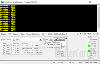
The code on the send_test sketch will repeatedly send a text message via Bluetooth. Open a terminal program like RealTerm and check that this message is being received. Don’t forget to set the correct port and baud rate. The default baud rate for the HC-05 module is 38400. If you see garbled characters instead of text, you are most probably using the wrong baud rate. The ports being used can be seen on your PC’s device manager. RealTerm can be downloaded here.

HC-05 Bluetooth module send test with RealTerm

Step 6 – Check the Bluetooth module is receiving 
Disconnect power to the Bluetooth module. Open the receive_test sketch on the Arduino IDE and upload it to the Arduino board. This code will make the led on the Arduino board turn ON or OFF when you send 1 or 0 from the terminal program. Once the upload is finished, reconnect power to the HC-05 Bluetooth module.

HC-05 Bluetooth module receive test with RealTerm

Press the Send tab in RealTerm, type 1 and press the Send as text button. The led on the Arduino board should turn ON. Now type 0 and press the Send as text button. The led on the Arduino board should turn OFF. 

That’s it for now! We successfully tested bi-directional Bluetooth communication between the Arduino and a PC. Next time we will learn how to read and change default HC-05 Bluetooth module settings. 

Buy the parts
Buy the Arduino UNO from Banggood
Buy the HC-05 Bluetooth module from Banggood
Buy resistors from Banggood
Buy the Arduino UNO from Dealextreme
Buy the HC-05 Bluetooth module from Dealextreme
Buy resistors from Dealextreme

I may get a small fee if you use the links to buy the parts. Thank you for your support!

Friday, April 28, 2017

Controlling relays with the Arduino

Today we are learning how to control relays with a microcontroller, using an Arduino. In this easy project we will program an Arduino board to switch On or Off any device you want, for example, an electrical appliance like a lamp, a heater or a fan. This is a simple but useful project, perfect if you are new to Arduino. Some knowledge of electronics and programming is a plus, but anyone can succeed in the Arduino world. So, what's an Arduino?

The Arduino platform
Arduino is an open-source electronics platform based on cheap but powerful and easy-to-use hardware and software. Arduino designs and manufactures microcontroller kits distributed as open-source hardware and software, permitting the manufacture of Arduino boards and distribution of the software by anyone. Being an easy tool for learning and fast prototyping, Arduino quickly gained success and has been used in thousands of different projects and applications by both beginners and advanced users.

To program the boards the Arduino project provides an IDE (integrated development environment), which includes a code editor, compiler and debugger. Arduino uses a custom programming language that is very similar to C and C++.

Arduino boards
There are several Arduino boards available, using mainly ATMEL and ARM processors. They vary in processing power, capabilities and  size. Usually Arduino boards are used together with other electronic devices like sensors, switches, displays, etc. These are manufactured in such a way as to easily connect with the Arduino boards. Many expansion shields are also available.

Arduino UNO, MEGA 2560, Nano and Lilypad
Popular Arduino boards (UNO, Nano, Mega 2560 and Lilypad).

Arduino relay control project
This project consists on controlling a relay with an Arduino board and a button switch. Once the board is programmed, pressing the button switch will turn the relay to the On or Off state, switching on or off whatever device is controlled by the relay. I will be using an Arduino UNO, but other Arduino boards (Nano, Leonardo, MEGA, etc) can be used.

Arduino relay control interconnects

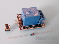
Relay, button and resistor
Hardware parts:
1x Arduino UNO board
1x Relay module (5V)
1x tactile button switch
1x 10KOhm resistor
Breadboard
Breadboard jumper wires

Notes:
This project uses a relay module that can be directly interfaced by an Arduino board. The relay used is not critical but it must be capable of handling the power that the appliance draws. In this tutorial a 10A relay module is used which can handle up-to 2400W (240Vx10A resistive loads) appliances. Relay coil is 5 Volts. This relay module has an led that lights up when the relay is switched on. Info on where you can buy the relay module is at the end of this post.

A breadboard makes hooking up the circuit easier, but is not essential.

How does it work?
Pressing the button switch momentarily will put pin 2 of the Arduino in HIGH (ON) state, with 5 Volts. This voltage will put the transistor in the relay module in the ON (conducting) state and that will then power the relay. When the relay is powered, the relay contacts will close and let mains power flow to our appliance. The opposite happens when the button is pressed again, pin 2 is put in LOW (OFF) state with 0 Volts and the relay is switched OFF. The controlled appliance is connected to two of the three terminal blue connector (the one with screws) on the relay module. 

Relay circuit


Step 1 - Download and install the Arduino IDE
There are two versions of the IDE, the offline one and the Arduino Web Editor. The traditional offline IDE will let you work without Internet connection. The Arduino Web Editor saves your work in the cloud and requires an Internet connection. In this tutorial I will be using the offline IDE. It can be downloaded here.  

Step 2 - Connect the circuit according to the schematic.
The circuit is really simple and all pins are labelled, both on the Arduino board and the relay module. It can all be put together using a small breadboard and some breadboard jump wires. The relay has 3 pins labelled -, + and S. Pin S is connected to an output pin on the Arduino, pin 2. The button switch has 4 pins, but 2 pairs are connected together! Check with a multimeter or, if the switch has no effect after the code is uploaded, try connecting to the other pins by rotating the switch 90º.

Step 3 - Connect the board to your computer.
Arduino boards use USB connection. If you are buying an Arduino board don't forget the correct USB cable. The Arduino UNO uses USB A to B cable (standard USB printer cable) and the Arduino Nano uses mini B USB plug.

Step 4 - Start the Arduino IDE
When the IDE is stated it will automatically create and name a file called a sketch. Sketch files is where we enter our code. Ignore the blank sketch file and download the project sketch file here. Then open the file in the IDE.

Step 5 - Select the board
Before uploading the sketch to the board we must make sure the correct type of board is selected in the IDE. Go to Tools > Board and select the correct board matching the board you are using.

Step 6 - Select the Port
Before uploading the sketch to the board select the correct communications port for the board. In the Tools menu, in Board, select the correct COM port.

Step 7- Upload the code
To upload the code to the Arduino board go to File and select Upload, or press the Upload button on the IDE toolbar. In a few seconds the code will be compiled and then uploaded to the board.

Arduino IDE

Testing
Once the code upload is completed you can test the circuit by pressing the switch button. You should hear the relay click on and off as you press the button.  If you use the suggested relay module, an led will also light up when the relay is switched on. If the switch has no effect, check the connections for errors or bad contacts and try rotating the tactile switch by 90º.

That's it! You now know how to use and program an Arduino to switch relays. You can use this project as it is or you can make changes to the code, like adding more relays or switching the relay On or Off at predetermined programmed times. Have fun!

Buy the parts and support MakerCorner!
I may get a small fee if you use the following links to buy the parts. Thank you for your support!


Thursday, April 6, 2017

72MHz-108MHz DIY FM Clock Radio Kit with digital display from Banggood

Few things are more fun to experiment with than "old style" radios! Peeking inside a radio is one of top things that sparks the interest of many young people in electronics!

Recently, while shopping for some electronics, an interesting FM radio kit came to my attention. It's an DIY (user assembled) FM radio with digital display and alarm clock. But what draw my attention to this kit was the fact that this radio can be easily modded to work outside of the commercial FM band and it has a digital frequency readout module that can be used in multiple radio projects! The radio is based on the popular CD2003GP/GB FM/AM radio IC. The digital frequency display uses the SC3610D IC, a frequency and clock display driver capable of up-to 150Mhz frequency display. Since the radio comes in kit form, it is also an excellent project to practice component assembling and soldering. 

DIY FM Radio Kit 72-108Mhz

There are two kits of this same radio, type 1 and type 2. They are identical, the only difference is that type 1 comes with the digital display module pre-assembled, which I recommend. Both kits cost around 9 USD with free shipping from Banggood. The radio operates from two AA batteries (3V), which are not included in the kit. 

cd2003 DIY FM radio kit schematic + pcb


FM radio kit assembly:
Assembly of FM radio kit is straightforward and should take well under two hours. All the necessary components are provided together with a big paper schematic of the radio circuit and parts list, which is excellent. Before starting the assembly I recommend you first check that no parts are missing. The kit that I received came with a few extra passive components and screws, which is a nice touch.

DIY FM radio kit components

Things you need:
To assemble the radio you will need a a low power soldering iron, 60/40 soldering wire, a wire cutter to trim the components leads after soldering and a small Philips screwdriver. Desoldering braid (wick) will also come handy if you need to desolder or remove excess solder from a joint.

Assembly steps:
  1. Start by inspect the main PCB and clean it if necessary. 
  2. Install the passive components on the board: resistors, capacitors, coils, etc. 
  3. Solder them in place and cut excess lead wires. 
  4. Install and solder the transistors and the two IC's. Be careful when soldering the IC's and transistors, since excessive heat can easily damage them! 
  5. Solder the speaker, antenna and battery wires to the PCB. 
  6. Place the metallic switch domes on the digital display board with some plastic tape and connect the digital display to the main board by soldering the wires. 
  7. Attach the speaker to the plastic case. 
  8. Place the plastic buttons and the two boards and insert the screws. 
  9. Attach the antenna wire to the antenna rod. 
  10. Solder the battery wires to the battery compartment.

Before inserting the batteries check if all components are in place and soldered properly. All solder joints should have a shiny finish!

That's it! Turn on the radio and try to tune to some FM radio station. 

I have made a video of the assembly process. Please take a look:


Tuning adjustment:
You may need to adjust the tuning capacitor to set the low and high FM band limits or to get the best reception quality. This is easily accomplished by tweaking two adjustment trimmers on the back of the tuning capacitor.

DIY FM Radio tuning adjustment


Improvements and Hacks:
The radio works reasonably well as it is, but you can make some improvements easily. You can even make the radio receive the Air Band (108-136Mhz). This is part of the fun of course.

Main components (datasheets):
CD2003GP FM/AM Radio IC datasheet
SC3610 Frequency and Clock Display Driver datasheet
TDA2822M Audio Amplifier IC Datasheet
 
Buy the kit and support MakerCorner!
I may get a small fee if you buy the kit through a link in MakerCorner. If you want to buy this kit and you found this post helpful, please support my work by clicking on this link to Banggood. Thank you!