In this post I'm going to test the ESP8266 ESP-01 WIFI module. I will demonstrate how to perform simple tests of the WIFI signal and serial communications with the module. This enables you to quickly check if a board is good or faulty.
The previous post was and introduction to the ESP8266 WIFI modules family. If you missed it, you can read it here: ESP8266 WIFI modules.
Let's get started!
The ESP8266 ESP-01:
This
module has inbuilt pcb antenna, 2 GPIO ports and pin header for
external connections. Signal range is up to 400 meters (in open range). The
board measures 14.3mm x 24.8mm. Prices start at around 2 USD for a
ESP-01 with 4Mbit RAM memory (8Mbit RAM is also available).
The ESP-01 module used for testing is made by AI-Thinker.com, but the testing procedures are identical for boards from other vendors.
The ESP-01 module used for testing is made by AI-Thinker.com, but the testing procedures are identical for boards from other vendors.
Testing the ESP8266:
When you buy one of these WIFI marvels you will want to perform a quick test to see if you received a good working device.
Testing the WIFI
The simplest test is to power the module and check if its WIFI signal is detected.
Connect the ESP-01 to a 3.3 Volts power source (GND and VCC pins). The module draws up to 170 mA when transmitting, so any power source capable of 170 mA will do the job.
After a few seconds your ESP8266 module should be listed as ESP_XXXXXX.
Testing the serial connection
Now we are going to test the wired serial communication between the ESP8266 and your computer. To do this we need to to connect the ESP8266 ESP-01 to a computer using the serial
connection (UART) and a USB to serial adapter.
Connect
the USB to serial adapter to the computer and check that it is
recognized by the O.S. If you are connecting the adapter to the computer
for the first time, you may need to install drivers. After the adapter
connects successfully, disconnect it from the computer.
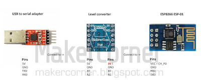
Since the ESP-01 board communicates using 3.3 volt logic levels and not the more common 5V most adapters use, we will also be using a logic level converter. If your serial to USB adapter supports 3.3v logic level then you do not need the level converter (or level shifter). Do not confuse UART logic level voltage with power supply voltage!
Connect the USB to serial adapter, level adapter and ESP8266 module as follows:
Most USB to serial adapters either have a jumper to set the power supply
line (VCC) to 5V or 3.3V or have separate 5V and 3.3V VCC pins. Some level converters also have a 5V to 3.3V voltage converter. You can set the power to 3.3V in USB to serial adapter and connect it to the ESP8266 module or, you can connect the 5V Vcc output from the serial to USB adapter to the 5V Vcc of the level converter and connect the 3.3V output of the level converter board to the VCC pin of the ESP8266.
Please note that it
IS possible to successfully connect the ESP-01 to the serial to USB
adapter without the level converter/shifter, but doing so may cause
unreliable operation or damage the ESP8266 board!
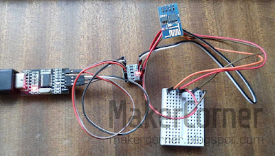
And this is how it may look after the connections are made. The small breadboard is not essential but, since we need to connect the ESP8266 CH_PD pin to a high logic level (3.3V), it is very handy.
To
"talk" to the module we can use several serial communication / terminal
programs or even the Arduino IDE. I will demonstrate using RealTerm. Realterm
is free and can be downloaded from sourceforge.
After
installing RealTerm, double check the boards connections and connect
the serial to USB adapter to your computer. The red led (power) on the
ESP8266 board should light up. The blue led should blink briefly. If the leds don't light up, unplug the USB
to serial adapter from the computer immediately and check the connections again.
In the RealTerm Port tab, check if the correct port is selected. You can check this in the O.S. device manager COM ports. Make sure that byte size, parity and flow control are the same as the following image.
Disconnect and reconnect the CH_PD connection, preferably in the breadboard. Some readable text, like vendor name and firmware version should be displayed.
If only garbled text is displayed it means RealTerm is not communicating correctly with the module. This probably caused by a speed mismatch. Select a different baud rate, press the Change button and disconnect and reconnect the CH_PD again. Repeat this until some legible text is displayed. Most modules seem to come with a default baud rate of 9600, so you may want to try 9600 baud first.
That's it for now! Next time we will learn how to send commands to the ESP8266 module and, amongst other things, change the baud rate (speed) of our board.
Documentation and tools:
Download RealTerm here.
Download ESP8266 datasheet here.
Further ESP8266 information, documentation and tools available on the Espressif Systems site.
List of ESP8266 modules and specifications of ESP8266 modules from AI-Thinker (not full list) can be downloaded here.
Buy the Parts:
Buy the ESP8266 Wi-Fi from Banggood
Buy the ESP8266 Wi-Fi from Dealextreme
Buy the USB to Serial Adapter from Banggood
Buy the USB to Serial Adapter from Dealextreme


No comments:
Post a Comment