Friday, December 9, 2016

Wi-Fi Internet Connected ThingSpeak.com Temperature Logger with ESP8266 + DS18B20 + NODEMCU

Today we are going make a remote Wi-Fi Internet connected temperature data logger using an ESP8266 WiFi module and a DS18B20 temperature sensor. The temperature readings will be automatically published at ThingSpeak.com and can be accessed from anywhere on Earth with Internet access. This is an easy and inexpensive project that almost anyone can successfully accomplish!

Hardware needed:
ESP8266 ESP-01 module (other ESP8266 modules can also be used).
DS18B20 temperature sensor.
1 4.7K 1/8w resistor.
Breadboard.
Breadboard wires.
Power supply (3.0 - 3.6 Volt).

The DS18B20 temperature sensor uses the 1-Wire bus that (as the name implies) requires only one data line for communication with a micro-controller. As you may recall from previous posts, the ESP8266 ESP-01 has 2 GPIO (General purpose In/Out ) ports and can be programmed to be used as a stand-alone device. So, to build a Wi-Fi one sensor temperature logger all we need is a ESP8266 module, a temperature sensor, one resistor and a power source. If we needed added functionality, for example also displaying the temperature reading in an LCD, then we would not use a stand-alone ESP8266, but we would connect it to an microcontroller board (like an Arduino). More advanced users could easily build a bare bones board with a microcontroller and a few discrete components.

ESP8266 + DS18B20 Temperature Logger
ESP8266 + DS18B20 Temperature Logger breadboard

DS18B20 pin assignment
The breadboard is not essential, just convenient for testing purposes. After all testing is done we would solder all the components together for minimum footprint.
  
For power source we have many options. We will choose a suitable power source based on where the sensor and module will be located and the autonomy needed. For testing purposes we can use a USB 5V to 3.3V voltage converter or two 1.5V fresh batteries in series. As long as it can deliver between 3V and 3.6V and 170mA, it will do.
 
The DS18B20 can be powered in two ways: external supply or parasite supply. Parasite power supply mode can be very useful if the sensor will be located far away from the Wi-Fi module. In parasite power mode the sensor gets its power from the sensor data line. There are caveats however, so read the DS18B20 datasheet carefully. In this circuit I will be using use a "normal" external power supply.


For the ESP8266 to work as a stand-alone device we need to use a module with bootable OS. For this project we will use the NodeMCU firmware, based in the eLua programming language. NodeMCU firmware can be obtained from GitHub. You can buy a ESP8266 module with NodeMCU already loaded or you can flash a "standard" ESP8266 with the NodeMCU firmware yourself. If you're like me you'll want to flash the firmware yourself. After all that's how we learn, by doing it ourselves!

If you don't know how to upload NodeMCU firmware to the ESP8266, please read my previous post.

After successfully flashing the ESP8266 with NodeMCU we will need to upload three additional files to the module: sensor.lua, ds18b20.lua and init.lua. Reading of sensor data is done by sensor.lua and ds18b20.lua.

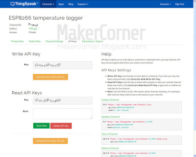
To publish the temperature sensor data on ThingSpeak.com you must first create an account with ThingSpeak and get an API key. After you create your account, click on the API keys tab to get them.

ThingSpeak API key

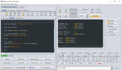
Copy the API write key and edit sensor.lua to add the key. Temperature reading interval set in sensor.lua and take place once a minute, but this can be changed. Init.lua should be the last file uploaded and, before you upload it, you must edit the file to add your Wi-Fi login information.


To upload the .lua files we can use ESPlorer or LuaLoader programs. In this example I'm using ESPlorer:

Uploading Lua files to ESP8266 NODEMCU with ESPlorer

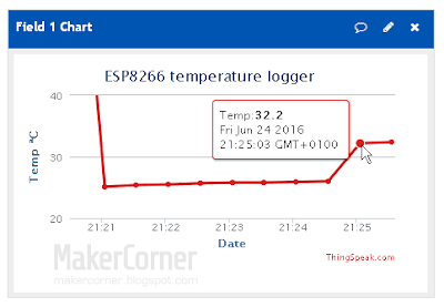
If all is OK, after the files are uploaded temperature readings will start and will be published on your ThingSpeak.com channel:

ThingSpeak temperature logger chart data
Congratulations! You now have an Internet connected temperature data logger!

Downloads:
DS18B20 datasheet
ESPlorer program
Lua files (sensor.lua, ds18b20.lua, init.lua)

Buy the parts and support MakerCorner!
I buy most of my electronics, tools and measuring equipment from Dealextreme and Banggood in China. They have low prices, friendly and helpful staff and will offer a solution if something goes wrong with your order. They have warehouses in Europe and the USA and can provide faster delivery for many of the items. I get a small fee if you buy from them through links in MakerCorner. So, please support my work by clicking on the following links. Thank you!

All parts are available in DX and Banggood, just click on the links and search for the part name on the web site.

Buy the parts from Dealextreme
Buy the parts from Banggood

Previous ESP8266 posts: 
ESP8266 NodeMCU firmware update
ESP8266 firmware update
ESP8266 ESP-01 testing - Part 2
ESP8266 ESP-01 testing - Part 1
ESP8266 WiFi modules


Saturday, June 25, 2016

ESP8266 NodeMCU firmware update

As we know from previous posts, the ESP8266 WiFi module can work as a standalone device. It's MCU, GPIO ports and user memory are all it's needed to make simple IoT projects like wireless Internet enabled data loggers.

For the ESP8266 to work as a standalone device we need to use a module with bootable OS. For this project we will use the NodeMCU firmware. NodeMCU is a firmware based in the eLua programming language for the ESP8266 from Espressif. The latest firmware is based on the Espressif NON-OS SDK 1.5.1.

You can buy a ESP8266 module with NodeMCU already loaded or you can flash a "standard" ESP8266 with the NodeMCU firmware yourself. If you're like me you'll want to flash the firmware yourself. After all that's how we learn stuff, by doing it ourselves!

NodeMCU firmware can be obtained from GitHub. It currently is made up of 41 modules. According to the team, due to the ever-growing number of modules available within NodeMCU, pre-built binaries are no longer made available. Now you select the modules you need, provide an e-mail address and the firmware will be custom built and sent to your e-mail. But older pre-built NodeMCU firmware versions are available. You can also built your own NodeMCU firmware. Fore more info go to the NodeMCU firmware GitHub project page.

To replace the ESP8266 firmware with NodeMCU we can use one of several flasher tools available. I will use the official tool from Espressif: ESP Flash Download Tool

Put the ESP8266 module in download mode and download the NodeMCU .bin firmware file to the 0x00000 address. You will need an USB to Serial adapter. If you don't know how to do this, read my previous post.


NODEMCU firmware flashing with ESP Flash download tool

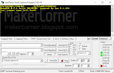
After the the firmware is successfully uploaded to the module we can check if the device is booting with NodeMCU. Disable download mode, start RealTerm and restart the module. In RealTerm you shoud get a Lua prompt:

RealTerm - NodeMCU firmware update success

Ignore the cannot open init.lua message, it's normal. It's shown because we did not upload a init.lua file yet. We'll do that when we upload Lua project files.

Downloads:
Download ESP FLASH DOWNLOAD TOOL
Download ESP8266 NodeMCU firmware
Download RealTerm

Buy the Parts:
Buy the ESP8266 Wi-Fi from Banggood
Buy the ESP8266 Wi-Fi from Dealextreme
Buy the USB to Serial Adapter from Banggood
Buy the USB to Serial Adapter from Dealextreme

Previous ESP8266 posts: 
ESP8266 firmware update
ESP8266 ESP-01 testing - Part 2
ESP8266 ESP-01 testing - Part 1
ESP8266 WiFi modules

Thursday, June 16, 2016

ESP8266 firmware update

If you have one or more of these little ESP8266 WiFi modules, sooner or later you will want to update their firmware. Espressif, the module's maker has been regularly releasing firmware updates introducing new functionalities and bug fixes. So, let's give it a try!

In previous posts I demonstrated how to connect the ESP8266 to a computer and test it. You may want to check it out if you don't yet know how to do that. Check the shortcuts at the end of this post.


Which firmware?


You can choose between firmware's with OS or without OS (NONOS). A firmware with OS will make your module a bootable device able to work by its own. You can even develop and upload a customized firmware. There are firmware's from different sources spread across the Internet, some quite suspicious. I recommend to go with a "trusted" source like AI-Thinker or Espressif. For this guide I will be using firmware from Espressif, the maker of the modules.

I am using a 4Mbit module and, at the time of writing, the latest firmware from Espressif that will "fit" this memory size is esp8266_nonos_sdk_v1.4.0_15_09_18_0. If your module has 8Mbit flash or more, you can update to a newer version. You can download ESP8266 firmware from Espressif here.


What firmware flasher tool?


To upload the firmware to the ESP8266 we can use several programs. I will be using the free ESP FLASH TOOL from Espressif, the maker of the modules. The latest version is 2.4, you can get it here.

ESP FLASH DOWNLOAD TOOL V2.4


Firmware download mode


Before the firmware can be uploaded, the ESP8266 module must be in firmware download mode. This is done by connecting GPIOØ pin to ground (GND).


Get ESP8266 module info


Once the module is in download mode, powered up and connected to a computer:

  • Check the correct COM port is selected in ESP FLASH TOOL. The default Baud rate should work. In case it doesn't try different values.
  • Click the START button.

The program should display SYNC in a green square left of the start button. It will retrieve the MAC address, memory size and crystal frequency, among other info. .


Select and upload firmware files


Now that we know the ESP flash download tool is communicating with our module:

ESP FLASH DOWNLOAD TOOL V2.4

  • Select the correct flash memory size and crystal frequency. Note: sometimes the program retrieves a wrong crystal frequency (24Mhz or 21Mhz for example).

Now, depending on the firmware we want to use, we need to select one or more files in the ESP Flash Download Tool Download Path Config panel. Each of these files must be loaded to the correct memory address. This information should be in a Readme file in the firmware archive file.

  • For each file needed, click the ... button of the correct memory address and navigate to the .bin file.
  • Check the selection box of each file/memory address.
  • Press START.

After a few seconds, if the upload was successful, the ESP Flash Download Tool will display FINISH.

Now that we successfully updated the firmware we must not forget to disable the firmware download mode by disconnecting the GPIOØ pin from ground!

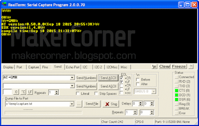
In RealTerm, sending the AT+GMR command will show the new firmware info: 

Verifying firmware update success in RealTerm

Be aware that the firmware upgrade might change the ESP8266 baud rate. In this case you must change the baud rate in RealTerm also!

I have uploaded a ESP8266 firmware upgrade video tutorial to YouTube. Please check it out and give it a thumbs up if you like it!


Downloads:
Download ESP FLASH DOWNLOAD TOOL
Download ESP8266 firmware
Download RealTerm

Buy the Parts:
Buy the ESP8266 Wi-Fi from Banggood
Buy the ESP8266 Wi-Fi from Dealextreme
Buy the USB to Serial Adapter from Banggood
Buy the USB to Serial Adapter from Dealextreme

Previous ESP8266 posts: 
ESP8266 ESP-01 testing - Part 2
ESP8266 ESP-01 testing - Part 1
ESP8266 WiFi modules

Saturday, May 28, 2016

ESP8266 ESP-01 testing - Part 2

Today we are going to learn how to communicate with the ESP8266 module through the serial (UART) connection using AT commands. 

In the previous post we learned how to connect the ESP8266 to a computer and test the serial and WIFI connection. If you need help hooking up your ESP8266 module take a look here: ESP8266 ESP-01 testing - Part 1

AT commands

Serial communication with the ESP8266 is done using AT commands. If you are not familiar with AT commands, they are instructions used to control modems. The ESP8266 is controlled the same way as a modem or GPS module. An instruction (or command) request is sent to the device to perform an action that once evaluated is executed (or not) and a "response" is given in return. The ESP8266 accepts many AT commands but today we are only going to use some of the most common ones. A full list of ESP8266 AT commands is provided at the end of this post.

The board used in this tutorial uses the stock firmware version .9.0.2 (00180008902) from AI-Tinker.com. Different firmware versions may behave differently. The AT commands list has also been updated since these boards where launched. If you are using a board with older firmware version and/or older AT commands version, newer AT commands will not be recognized! Like with firmware, the ESP8266 board AT list can be updated.

Let's get started!


Test AT startup


The first command we are going to send to the ESP8266 board is simply AT. It's used to test the startup function of our ESP8266 module. In RealTerm:
  1. Click the Send tab.
  2. Type AT in the first textbox.
  3. Check the  +CR and +LF.
  4. Press the Send ASCII button.

The ESP8266 board should respond with an OK message. This tells us the command was received and the serial communication is ready and working.

ESP8266 AT command

View version information


Now lets find out what is the firmware version of our ESP8266 board. Send the AT+GMR command.


This board uses firmware version .9.0.2 (00180008902). This is an old firmware version.

Note: the version information displayed depends on the firmware running on the board. Newer firmware versions display the firmware version and the AT commands version.
 

Change baud rate


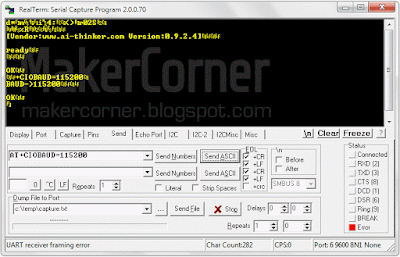
Lets change the ESP8266 baud rate, or the speed of the serial communication. Let's try 115200 baud. Type AT+CIOBAUD=155200 and press the Send ASCII button. The ESP8266 should output the following text which confirms the new baud rate was accepted:

ESP8266 baud rate AT+CIOBAUD command

Notes:
Newer boards accept two sets of serial parameters: AT+UART_DEF (default params, saved on the board memory) and AT+UART_CUR (current params, not saved).

Now the ESP8266 serial interface is running at 115200 baud. Since we changed the baud rate in the ESP8266 module we must also change the baud rate in RealTerm to 155200!

ESP8266 baud rate AT+CIOBAUD command

The new baud rate was set and stored in the ESP8266 memory. From now on, every time the board is started or restarted it will default to 115200 baud rate. 

We can also ask our ESP8266 module what the baud rate is. To do this we send the command AT+CIOBAUD?  

ESP8266 baud rate AT+CIOBAUD? command

Other AT commands you might want to test:

AT+RST – Restart module;
AT+RESTORE – Factory reset.


Wi-Fi related AT commands


Before trying out WiFi commands we should get familiar with the different WiFi modes. As we know, the ESP8266 supports three modes: station mode, softAP (virtual access point) mode and station mode + softAP mode. In station mode the ESP8266 works as a network device and can connect to an existing wireless network (router). In softAP mode the ESP8266 behaves as a wireless router and can be connected to by network devices.When operating in both modes (softAP + station mode), the ESP8266 can act as network repeater.

Set WiFi mode


The default ESP8266 WiFi mode is softAP (2). To know what mode your ESP8266 module is in, send the command AT+CWMODE?

According to what WiFi mode the ESP8266 is on it will respond with 1 : station mode, 2 : softAP mode or 3 : softAP + station mode.


To set to a particular WiFi mode send AT+CWMODE=X, where X is the mode you want to set.

To use the next WiFi commands the ESP8266 must be in mode 1 or mode 3, so change to station mode (mode 1), sending  AT+CWMODE=1.

ESP8266 set WiFi mode AT+CWMODE command

Note:
AT+CWMODE will not be recognized by boards with firmware from Espressif, use AT+CWMODE_CUR or AT+CWMODE_DEF instead.

Get list of available WiFi access points in our location


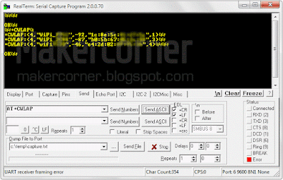
Type and send the command AT+CWLAP. The  ESP8266 will scan the WiFi frequency range and list all the access points in range. Each line item consists of the security level of the AP, network name, signal strength, MAC address and WiFi channel.

ESP8266 get list of WiFi AP's AT+CWLAP command

Security Modes:
0 Open
1 WEP
2 WPA_PSK
3 WPA2_PSK
4 WPA_WPA2_PSK

Note:
If the you get an AT+CWLAP ERROR set the ESP8266 to station mode or softAP + station mode.

Join access point


To join an access point we can use the command AT+CWJAP="SSID","Password".SSID is the

ESP8266 join AP AT+CWJAP command

After a few seconds the ESP8266 should respond with OK if successful or FAIL if unsuccessful. After the board joins an access point, it will store that AP SSID and password and automatically join that access point every time the board starts up! To stop this, simply disconnect from the AP before powering of the board.

Note:
This command has been deprecated. If your board uses firmware from Espressif use AT+CWJAP_CUR or AT+CWJAP_DEF instead. See the Espressif ESP8266 AT commands list for details.

Disconnect from AP


To disconnect our ESP8266 from an access point simply send the AT+CWQAP command.


Documentation and tools:
Download RealTerm here.
Download AI-Thinker AT commands list here (unofficial).
Download Espressif ESP8266 AT commands list here.

Buy the Parts:
Buy the ESP8266 Wi-Fi from Banggood
Buy the ESP8266 Wi-Fi from Dealextreme
Buy the USB to Serial Adapter from Banggood
Buy the USB to Serial Adapter from Dealextreme

NEXT: ESP8266 firmware update
PREVIOUS: ESP8266 ESP-01 testing - Part 1

Saturday, May 21, 2016

ESP8266 ESP-01 testing - Part 1

In this post I'm going to test the ESP8266 ESP-01 WIFI module. I will demonstrate how to perform simple tests of the WIFI signal and serial communications with the module. This enables you to quickly check if  a board is good or faulty.

The previous post was and introduction to the ESP8266 WIFI modules family. If you missed it, you can read it here: ESP8266 WIFI modules.

Let's get started!


The ESP8266 ESP-01:

ESP8266 ESP-01 WIFI module

This module has inbuilt pcb antenna, 2 GPIO ports and pin header for external connections. Signal range is up to 400 meters (in open range). The board measures 14.3mm x 24.8mm. Prices start at around 2 USD for a ESP-01 with 4Mbit RAM memory (8Mbit RAM is also available).

The ESP-01 module used for testing is made by AI-Thinker.com, but the testing procedures are identical for boards from other vendors.

Testing the ESP8266:

When you buy one of these WIFI marvels you will want to perform a quick test to see if you received a good working device. 

Testing the WIFI

The simplest test is to power the module and check if its WIFI signal is detected. 
Connect the ESP-01 to a 3.3 Volts power source (GND and VCC pins). The module draws up to 170 mA when transmitting, so any power source capable of 170 mA will do the job.

ESP8266 pinout

 
WARNING: The ESP8266 power supply (Vcc) requires 3.0v to 3.6v. Never connect it to 5 Volts! 


ESP8266 WIFI connection test

After a few seconds your ESP8266 module should be listed as ESP_XXXXXX.

Testing the serial connection

Now we are going to test the wired serial communication between the ESP8266 and your computer. To do this we need to to connect the ESP8266 ESP-01 to a computer using the serial connection (UART) and a USB to serial adapter.

USB to TTL RS232 serial adapter
Connect the USB to serial adapter to the computer and check that it is recognized by the O.S. If you are connecting the adapter to the computer for the first time, you may need to install drivers. After the adapter connects successfully, disconnect it from the computer.

Checking USB to serial adapter COM port in Device Manager

Since the ESP-01 board communicates using 3.3 volt logic levels and not the more common 5V most adapters use, we will also be using a logic level converter. If your serial to USB adapter supports 3.3v logic level then you do not need the level converter (or level shifter). Do not confuse UART logic level voltage with power supply voltage!

4bit level converter board


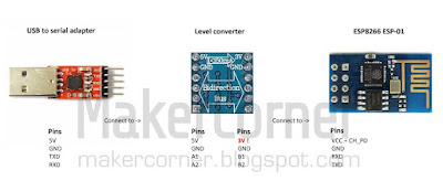
Connect the USB to serial adapter, level adapter and ESP8266 module as follows:

ESP8266 USB to serial adapter level converter test connections

Most USB to serial adapters either have a jumper to set the power supply line (VCC) to 5V or 3.3V or have separate 5V and 3.3V VCC pins. Some level converters also have a 5V to 3.3V voltage converter. You can set the power to 3.3V in USB to serial adapter and connect it to the ESP8266 module or, you can connect the 5V Vcc output from the serial to USB adapter to the 5V Vcc of the level converter and connect the 3.3V output of the level converter board to the VCC pin of the ESP8266.

Please note that it IS possible to successfully connect the ESP-01 to the serial to USB adapter without the level converter/shifter, but doing so may cause unreliable operation or damage the ESP8266 board!

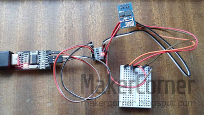
And this is how it may look after the connections are made. The small breadboard is not essential but, since we need to connect the ESP8266 CH_PD pin to a high logic level (3.3V), it is very handy.

ESP8266 serial test connections


To "talk" to the module we can use several serial communication / terminal programs or even the Arduino IDE. I will demonstrate using RealTerm. Realterm is free and can be downloaded from sourceforge.

After installing RealTerm, double check the boards connections and connect the serial to USB adapter to your computer. The red led (power) on the ESP8266 board should light up. The blue led should blink briefly. If the leds don't light up, unplug the USB to serial adapter from the computer immediately and check the connections again.

In the RealTerm Port tab, check if the correct port is selected. You can check this in the O.S. device manager COM ports. Make sure that byte size, parity and flow control are the same as the following image.


Disconnect and reconnect the CH_PD connection, preferably in the breadboard. Some readable text, like vendor name and firmware version should be displayed. 


If only garbled text is displayed it means RealTerm is not communicating correctly with the module. This probably caused by a speed mismatch. Select a different baud rate, press the Change button and disconnect and reconnect the CH_PD again. Repeat this until some legible text is displayed. Most modules seem to come with a default baud rate of 9600, so you may want to try 9600 baud first. 


That's it for now! Next time we will learn how to send commands to the ESP8266 module and, amongst other things, change the baud rate (speed) of our board. 

Documentation and tools:
Download RealTerm here.
Download ESP8266 datasheet here.
Further ESP8266 information, documentation and tools available on the Espressif Systems site
List of ESP8266 modules and specifications of  ESP8266 modules from AI-Thinker (not full list) can be downloaded here.

Buy the Parts:
Buy the ESP8266 Wi-Fi from Banggood
Buy the ESP8266 Wi-Fi from Dealextreme
Buy the USB to Serial Adapter from Banggood
Buy the USB to Serial Adapter from Dealextreme

NEXT: ESP8266 ESP-01 testing - Part 2
PREVIOUS: ESP8266 WiFi modules

Wednesday, May 18, 2016

ESP8266 WiFi modules
The ESP8266 Wi-Fi modules are tiny low-cost boards comprising a Wi-Fi radio transceiver, a 32 bit micro-controller and flash memory. They are programmable and can be connected to computing devices (Arduino and others) or used as standalone devices.

At the heart of the modules is the ESP8266EX chip which integrates an enhanced version of Tensilica’s L106 Diamond series 32-bit RISC processor. The MCU runs between 80-160Mhz, has low power consumption and two power saving modes. It is a complete and self-contained WiFi networking solution, can work as an Wi-Fi adapter or integrated with external sensors and other application specific devices through its GPIO's.

The ESP8266 is available in several configurations, with more or less memory, more or less I/O (GPIO) ports, different antennas, with or without shielding and with or without connection header. Most of these modules are named ESP-01 to ESP-14. The smallest is just 10x10mm!

Target applications for the ESP8266 are mobile devices, wearable electronics and the Internet-of-Things (IoT): home appliances, home automation, smart plug and lights, IP cameras, baby monitors, sensor networks, etc.

ESP8266 ESP-01 ESP-02 ESP-03 ESP-04 ESP-05 ESP-06 ESP-07 ESP-08 ESP-09 ESP-10 ESP-11

Recently (April 2016) AI-Thinker has released the ESP 32 series, ESP 85 series (ESP8285) and ESP-S series of WIFI modules.

MAIN FEATURES:
WiFi 2.4Ghz;
802.11 b/g/n protocol;
Wi-Fi modes: station/softAP/SoftAP+station;
Support STA/AP/STA+AP operation modes;
Integrated TCP/IP protocol stack;
Security: WPA/WPA2;
Encryption: WEP/TKIP/AES;
Low power consumption 32-bit MCU;
10-bit ADC;
UART serial connection;
Power supply: 3.3 Volts

The ESP8266 is designed by Espressif Systems, a fabless semiconductor company from Shangai, China. Initially modules where made by AI-Thinker but now they are available from other vendors also. They can be bought from dealextreme, banggood, ebay and may other places.

Documentation and tools:
Download ESP8266 datasheet here.
Further ESP8266 information, documentation and tools available on the Espressif Systems site
List of ESP8266 modules and specifications of  ESP8266 modules from AI-Thinker (not full list) can be downloaded here.

NEXT: ESP8266 ESP-01 testing - Part 1

Saturday, May 7, 2016

Welcome to the maker corner!

Hi, welcome to the Maker Corner!

In the Maker Corner I will be sharing my passion of electronics, computers and programming with you. I like all things electronic and I love to tinker with equipments and devices in order to improve or customize them. I am also an Arduino fan and will be sharing some projects and reviewing electronic modules and sensors.

I hope you enjoy the Maker Corner blog!